Process Analyzer Sample Probe Assembly (SPA) with Conax Technologies Packing Gland (PG)
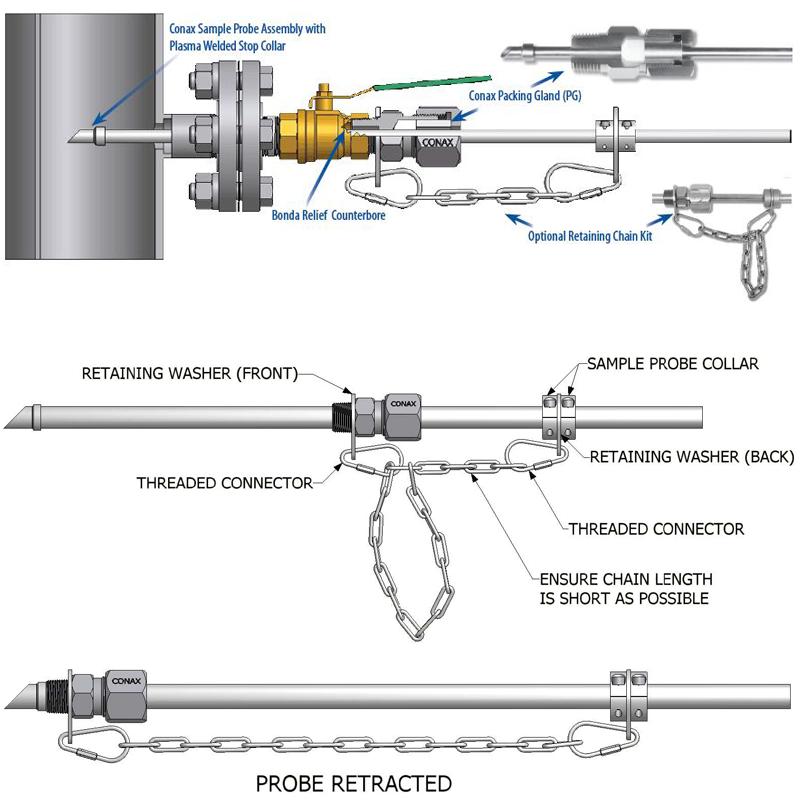
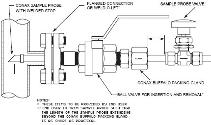
The Conax Technologies Sample Probe Assembly (SPA) is used to hot-tap a probe into a process through a process isolation valve as depicted below.
Optional materialsOptional materials for the Sample Probe and the Conax Technologies Packing Gland body (wetted components) are available. Refer to the Conax Pressure and Vacuum Sealing Assemblies Catalog #5001B or our website for available options such as:
- 316L SST
- 316 NACE SST
- 316L CRN (gland body only)
- Monel 405
- Hastelloy C276
- Inconel 600
Temperature and Pressure Ratings
Refer to the Conax Pressure and Vacuum Sealing Assemblies Catalog #5001B for temperature and pressure ratings for static conditions. Pressure ratings are reduced when the sealing gland cap is loosened to allow for the insertion or extraction of the Sample Probe.
How to Configure the Model Number of an SPA Assembly
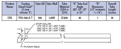
Standard Conax Packing Gland (PG) model numbers and configurations apply. Sealing glands are supplied loose unless otherwise indicated. Example model number: SPA/PG5-500-A-T/500X120W(S304)-45-1-36
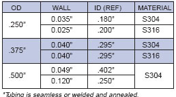
Standard Tube Sizes*
Other sizes and materials available on request.
Additional Considerations
Caution. The end user must take the necessary safety precautions when loosening the cap of the Conax sealing gland when inserting or extracting the Sample Probe into pressurized environments. The end user is responsible to control any leakage of process fluids that may occur during insertion or extraction of the Sample Probe. The end user is responsible for determining the appropriate Sample Probe material, diameter and wall thickness for the process environment and flow rates.
Conax Technologies Technologies is not responsible for the operation of the Conax Packing Gland (PG) assembly once the cap is loosened to allow for the insertion or extraction of the Sample Probe.
Typically, when properly installed, the angled Sample Probe tip should have the long side upstream. This reduces the particulates entering the Sample Probe and into the process analyzer filter. The Sample Probe immersion length should be designed to obtain a process sample close to the center of the pipe. It is suggested that the end user mark the Sample Probe end with an indelible ink marker relative to the angled end for proper orientation into the process.